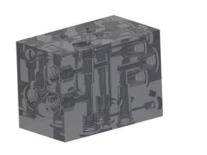
Valve manifold
A CAD illustration of a valve manifold from the Salus portfolio. For a new block, the circuit, port arrangement, mounting and test scope are defined for the specific application.
 Hydraulic systems & controls
Salus design portfolio
Examples previously presented in the Salus Hydraulics portfolio. These are CAD illustrations, not photographs of completed installations.
A CAD illustration of a valve manifold from the Salus portfolio. For a new block, the circuit, port arrangement, mounting and test scope are defined for the specific application.
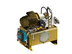
A power-unit design example showing the pump drive, reservoir and hydraulic control assembly. Power, flow and reservoir requirements are agreed for the duty cycle.
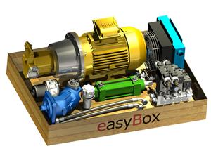
A compact system concept presented in the Salus portfolio. Installation space, access to components and connection points are part of the design discussion.
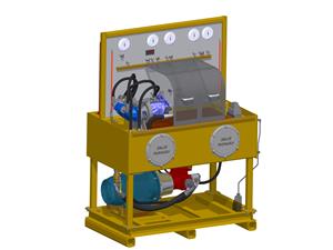
A test-equipment design example. The quantities to measure, operating range, instrumentation and test sequence need to be defined before a new station is specified.
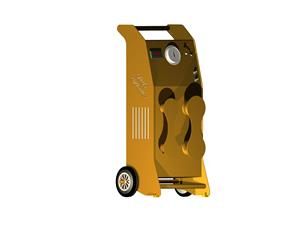
A nitrogen-transfer equipment design example from the Salus portfolio. Any new pressure-equipment project requires its own technical specification and agreed responsibilities.
Send the machine function and installation constraints. We will discuss the scope, including design, component supply, assembly, testing and commissioning where required.